Tool Guide:
This tool is meant to be used as guidance for understanding the radiation risks that apply to a specific set of circumstances, not to replace modeling one's own environment or replacing the need to test a device or system. When used from start to finish you can obtain guidelines to help mitigate radiation effects and understand where you can avoid risks, based on simplified inputs, for a part in question. The tool outputs are reactive to the user inputs and will change accordingly to help identify relative risks and hazards and can be used to create a parts list capturing all of the inputs and outputs.
Each Navigation Tab is a step in the process:
1. User Mission - Begin with selecting the options that apply to you for an intended mission, each input will directly impact the output of the tool that is to follow. At any time, you can choose to begin again, or follow the path for a new mission design under question. By selecting a mission class, lifetime, orbit, and architecture you are returned an environment severity with contributions and the EEE threats the tool will focus on.
2. Environment Comparison - Using the inputs from section 1, the tool displays past mission modeling efforts that have been done. It returns the details of a mission that has been calculated to be close to yours when normalized for one year. This panel allows selection of multiple missions to compare and explore. It should be noted that the Solar cycle has an impact on the dose based on the launch year, and the normalization is for approximation. Two plots are available, the TID vs. shielding depth curve and the GCR spectra. The tool also returns data tables for all plots rendered. This piece of the tool is to show how shielding can be used to mitigate dose levels, and how mission characteristics impact your SEE concerns.
3. Device Response -Using the top level selections from section 1, the device susceptibility and basic radiation concerns are called out when the user inputs the device information. Here the tool returns examples of the most prevalent radiation concerns through experience with families of results on device types.
4. Guidelines -The final step captures radiation line of questioning that is tailored to the user inputs, the major concerns are clarified and the user is presented with mitigation strategies. You can also see a listing of class guidelines with respect to radiation. In an effort to document failure modes and reduce the threat/risk to the system from a radiation standpoint, a line of risk pre and post mitigation is returned. All of the tools inputs and outputs can be saved and added to a table. The user can then choose to add another part to build a parts list.
Upon first use look for the blue buttons to progress. Hover over user inputs for some additional context. See User Guide for more details.
Due to the fact that radiation effects are application specific, this guidance is notional, generalizations cannot cover the entire state-space and the user will benefit from a more detailed analysis.
Commonly Used Definitions/Acronyms in Radiation Analysis:
Energy Deposition:
Total Ionizing Dose (TID) - the mean energy imparted by ionizing radiation to a sensitive device region divided by the mass of the region. This is typically given in units of rad(Si), where 1 rad(Si) = 100 erg deposited per gram of silicon.
Non-Ionizing Energy Loss (NIEL) - is defined as the part of the incident particle energy consumed. Through Coulombic, nuclear elastic, and nuclear inelastic interactions that can occur between the incident particle and the lattice atoms, to produce vacancy-interstitial pairs (i.e., displacement damage)
Displacement Damage Dose (DDD) - the cumulative damage of the semiconductor lattice caused by ionizing radiation's non-ionizing energy loss over the time of exposure. Displacement energy per unit mass, this is typically given in units of rad(Si), where 1 rad(Si) = 100 erg deposited per gram of silicon.
Linear Energy Transfer (LET) - a measure of the energy deposited per unit path length as an energetic particle travels through a material. The common LET unit is MeV-cm 2 /mg of material (Si for MOS devices, etc.).
Threshold LET (LET th ) - the maximum LET tested where no single event was recorded to a particle fluence of 1x10 7 ions/cm 2
Orbits:
Low Earth Orbit (LEO) - Earth Orbits ranging from 160 km to 2,000 km, 'polar' would be at an inclination near 90 degrees, 'equatorial' is of a lower inclination
Geosynchronous Earth Orbit (GEO) - an Earth orbit with a period of one sidereal day, geostationary is a special case given a circular orbit in the plane of the Earth's equator. These orbits share a semi-major axis, if circular the altitude is then 35,786 km.
Medium Earth Orbit (MEO) -Orbits ranging from an altitude of 2,000 km to that of GEO.
Single Event Effects:
Single Event Effect (SEE) - any measurable effect to a circuit due to a strike by a single ion. Such effects include (but are not limited to) SEUs, SHEs, SELs, SEBs and SEGRs.
Single Event Gate Rupture (SEGR) - a single ion induced condition in power MOSFETs that may result in the formation of a conducting path in the gate oxide.
Single Event Latchup (SEL) - a condition that causes loss of device functionality due to a single event induced high current state. An SEL may or may not cause permanent device damage, but requires power strobing of the device to resume normal device operations.
Single Event Functional Interrupt (SEFI) - a condition of repeated error states such that a reset is needed to clear the device.
Multiple Bit Upset (MBU) - an event induced by a single energetic particle such as a cosmic ray or proton that causes multiple upsets or transients during its path through a device or system.
Single Event Burnout (SEB) - a condition that can cause device destruction due to a high current state in a power transistor.
Single Event Upset (SEU) - a permanent or transient change of state induced by an energetic particle such as a cosmic ray or proton in a device. This may occur in digital, analog, and optical components. These are 'soft' errors in that a reset or rewriting of the device causes normal device behavior thereafter.
Single Event Transient (SET) - a transient change of state induced by an energetic particle such as a cosmic ray or proton in a device. This may occur in digital, analog, and optical components and may have effects in surrounding interface circuitry. These are 'soft' errors in that a reset or rewriting of the device causes normal device behavior thereafter.
Single Hard Error (SHE) - an SEU that causes a permanent change to the operation of a device. An example is a stuck bit in a memory device.
Galactic Cosmic Ray (GCR) -High energy radiation originating from outside of our Solar System.
Solar Particle Events (SPE) -High energy radiation events originating from our Sun during flares or coronal mass ejections.
Begin Mission Analysis
What are the Notional Radiation Risks?
Mission Description:
Overview:
Environment Severity:
EEE Focus on:
Many thanks to Ken LaBel & Jonathan Pellish
What Does a Similar Environment Look Like?
User Selection:
Your Orbit Input:
kmSimilar to:
There is no substitute for modelling your own environment with accurate details like launch date, orbit, and duration [2]. The aggregation of the tools used and resources available have made the state of the practice approachable after familiarization. Seek expert inputs when dealing with unique environments, such as spiral orbits through the belts (electric propulsion) [3] Jovian orbits (harsh radiation belts), Lunar surface (albedo), etc.
There exist software for analysis of more complex geometries and transport through different materials, search for radiation ray-tracing for more details.
Outputs:
GCR Flux vs. LET
For Cumulative Effects - While ionizing radiation is often referred to in part designations and ratings, non-ionizing radiation damage must also be considered. Displacement Damage Dose can be a driving failure mechanism depending on device process and function. It too will be a function of mission parameters, shielding, as well as non-ionizing energy loss of the incident particle:
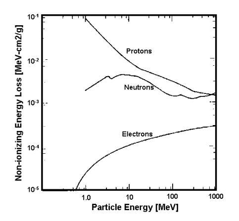
NIEL in silicon of different particle types [1]
For SEE - While GCR flux are continuously present for a given orbit, our nearby environment is not in a steady state, the dynamicism of solar events must also be considered. Fluxes can be orders of magnitude higher for windows of time during and after these events:
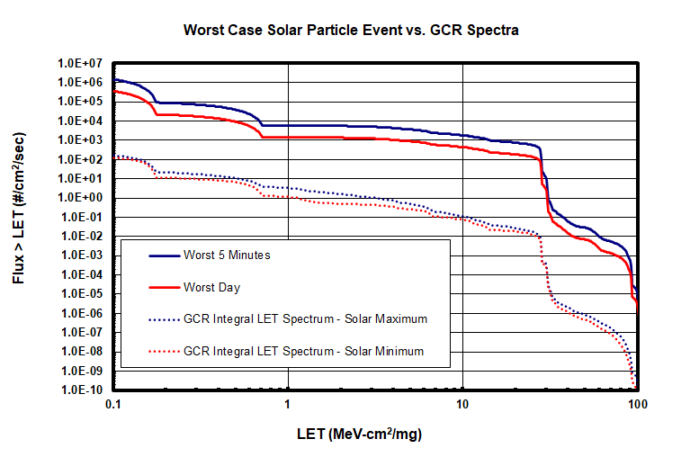
Outputs from CREME96 calculations for GCR (dotted lines) and Solar-energetic particle ("flare") conditions (solid lines) for worst day and worst 5-minute intervals during the October 1989 event.
Results can be found using tools like
SPENVIS
CREME
OMERE
TID and Flux are often quoted behind 100mils Al
See also:
Cross-Program Design Specification for Natural Environments
Many thanks to Mike Xapsos & Craig Stauffer
How do Similar Devices React?
User Device Input:
Notional Threat Identification:
For your device inputs of:
Mission specific radiation concerns by family are:
Typical function responses are:
Search for Test Data:
Radiation report resources (first place to look for your part number):
NASA GSFC Radiation Effects and Analysis GroupNASA Electronic Parts and Packaging
PMPedia
S3VI
Having applicable data enables informed analyses like rate calculations or optimization of shielding.
Many thanks to Kaitlyn Ryder & Ray Ladbury
What should you do to bring down the risk?
Programmatic Guidance:
Notional Class Guidelines:
- Paraphrased from GPR 8705.4, under NPR 8705.4Radiation Hardness Assurance:
Mission Environment, Application, and LifetimeAvionics Radiation Hardness Assurance Guidelines
COTS Specific Guidance:
Based on Criticality vs. Environment:
- Originally from the NEPP 3x3Part Selection:
JPL COTS in Radiation EnvironmentsIn addition a Model Based Mission Assurance (MBMA) approach can extend this type of analysis, visit SEAM to learn more.
Application Questions:
Specific Recommendations:
Recommendation and Guidelines:
Many thanks to Christina Seidleck & Caroline Fedele
References:
Publications:
[1] C. J. Dale, P. W. Marshall, E. A. Burke, G. P. Summers, and E. A. Wolicki, "High energy induced displacement damage in silicon," IEEE Trans. Nucl. Sci., vol. 35, pp. 1208-1214, 1988.
[2] K. A. LaBel, A. H. Johnston, J. L. Barth, R. A. Reed and C. E. Barnes, "Emerging radiation hardness assurance (RHA) issues: a NASA approach for space flight programs," in IEEE Transactions on Nuclear Science, vol. 45, no. 6, pp. 2727-2736, Dec. 1998, doi: 10.1109/23.736521.
[3] Y. Shin, et al., Radiation effect for a CubeSat in slow transition from the Earth to the Moon, Advances in Space Research, Volume 55, Issue 7, 2015, Pages 1792-1798, ISSN 0273-1177.
The radiation effects community publishes regularly in IEEE Transactions on Nuclear Science which is searchable through IEEE Xplore.
Acknowledgements:
Beyond the inspiration thank yous at the bottom of each page, countless others have given feedback and direction to make this tool as useful and informative as it is. Support from NASA Electronics Parts & Packaging, professors at Vanderbilt, and the radiation effects subject matter experts across the agency is deeply appreciated.
Links:
Databases:
NASA Technical Reports Server (NTRS)NASA GSFC Radiation Effects and Analysis Group
NASA Electronic Parts and Packaging
PMPedia
NASA Documents:
MSFC DSNEJPL Selection of COTS in Radiation Environments
NESC MEAL
NESC Avionics RHA
NPR 8705.4
Open Engineering Tools:
CREMEOLTARIS
OMERE
SEAM
SEU Weibull Fit
SPENVIS
SRIM
Small Missions:
S3VISmallSat RHA
Knowledge Repositories